
What is Advanced Power Flow Control?
February 7, 2024
Advanced power flow control (APFC) uses power-electronics-based equipment to change how electricity flows across transmission circuits. By adjusting a circuit’s effective reactance, it can move power away from a constrained path and make better use of available capacity elsewhere in the network.
This article explains the technology, where it can help, and examples of SmartValve deployments. Additional capacity depends on the network and operating conditions; it must be established through project-specific studies.
How does advanced power flow control work?
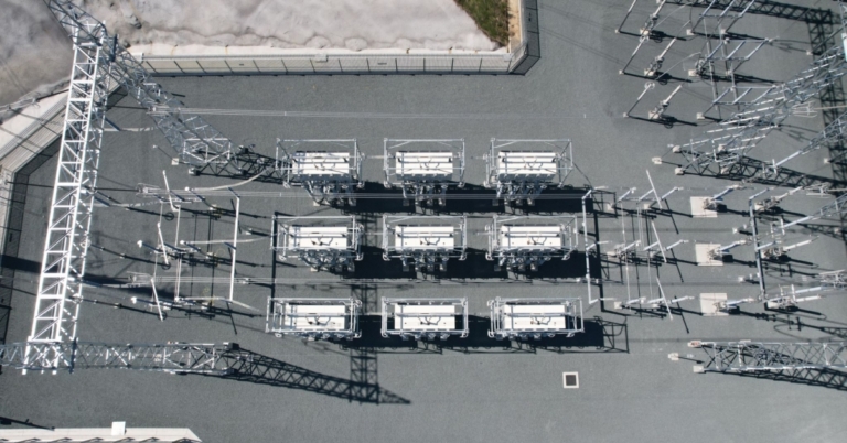
SmartValve is a modular static synchronous series compensator (m-SSSC). It injects a voltage in quadrature with line current to synthesize a capacitive or inductive reactance. This lets operators increase or decrease the effective reactance of the circuit and control its power flow.
In a meshed network, that control can shift flows away from heavily loaded circuits and onto electrically useful paths with available capacity. Planning and operational studies establish the usable transfer capability, relevant contingencies, control settings, and any remaining thermal, voltage, or stability limits.
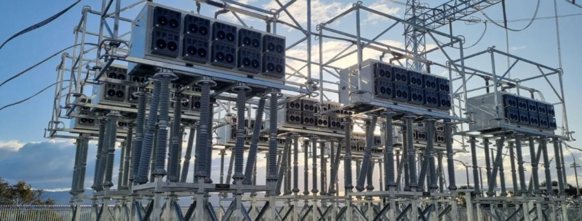
SmartValve uses voltage-sourced converter technology. Its modular design allows a deployment to be expanded, and modules can be relocated if network needs change, subject to the engineering and site requirements. Bypass arrangements allow individual modules to be taken out of service; the resulting installation capability depends on the available modules and system design.
Dynamic performance and integration requirements should be evaluated for the intended application, including protection, controls, communications, and operator procedures.
Technical background: EPRI’s 2020 Central Hudson pilot evaluation describes the m-SSSC operating principle and integration considerations. That pilot report is technical evidence for its evaluated scope, not a guarantee for other deployments.
How can it help operators?
Illustrative network example: The loading percentages and 200 MW figure in the following schematic are example values, not measured results from a customer deployment or a prediction for another network.
This simplified graphic of an area of a transmission grid shows how APFC can be used to balance power flows and maximize use of the grid while a line is out-of-service for reconductoring. It depicts just one of many possible applications of APFC.
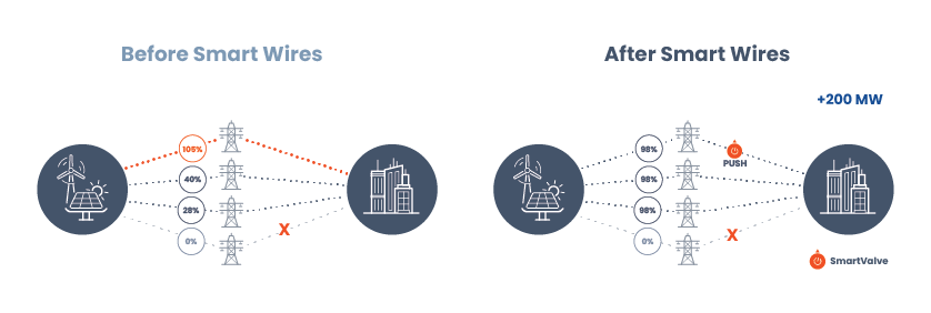
In scenario A, a transmission line is out-of-service for maintenance which is causing overloads on a parallel transmission line (108%). This overloaded line is acting as a bottleneck, limiting the capacity of the network and resulting in constraints on the output of the renewable energy generation site.
In scenario B of this simplified illustration, APFC changes how power is shared between the circuits, reducing the loading on the limiting path and using available capacity on another path. The example depicts 200 MW of additional transfer capability. A real project’s usable capacity and operating controls must be established through network studies, including the required contingencies and any remaining limits.
Where is advanced power flow control used?
Smart Wires’ SmartValve technology is used in transmission networks in multiple regions. The examples below describe different applications; each project has its own network conditions, scope, and results.
In the U.S., FERC’s Order 2023 explainer describes evaluation of alternative transmission technologies, including APFC, in generator interconnection cluster studies. Evaluation does not require selection of a particular technology or supplier.
United States
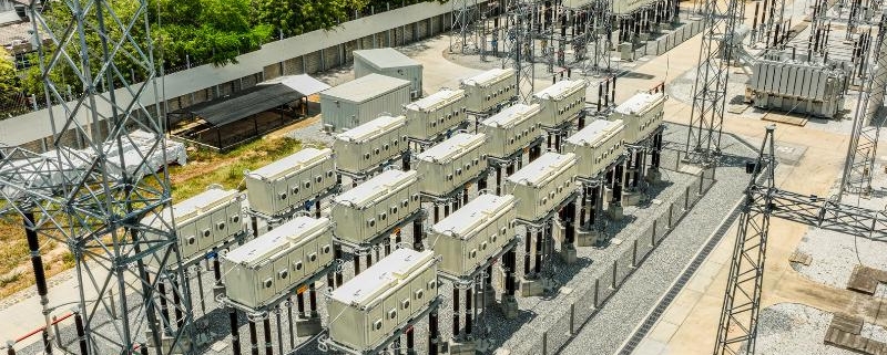
Central Hudson reports installing 15 SmartValves at Hurley Avenue to make 185 MW of additional grid capacity available. The utility also reports estimated savings of $10 million compared with other options, a smaller footprint, and a quicker installation. These are project-specific results and comparisons.

Colombia
Smart Wires’ ISA TRANSELCA project report describes using APFC to address transmission congestion affecting renewable generation in northern Colombia. The project illustrates a specific network application; its cost and delivery comparisons should not be generalized to other systems.
Australia
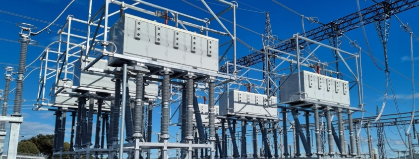
Transgrid’s VNI Minor project announcement explains the use of power flow controllers at Stockdill and describes a planned 170 MW increase in transfer capability under relevant network conditions. That figure relates to the upgrade project. It is not a universal SmartValve rating.
United Kingdom
National Grid’s May 2024 announcement describes SmartValve installations across three substations and five circuits in northern England to improve use of its transmission network. This is evidence of a specific congestion-relief application, not a promise of the same capacity, savings, or schedule elsewhere.
Questions about power flow control
What is power flow control in an electricity network?
Power flow control changes how electricity is distributed across network paths. In a meshed AC grid, controlling the electrical characteristics of a circuit can shift flows away from a constrained path and onto paths with available capacity. DOE describes this role in its overview of grid-enhancing technologies.
What does APFC mean here?
On this site, APFC means advanced power flow control for electricity transmission. It is different from automatic power factor correction, another use of the same acronym. SmartValve is Smart Wires’ modular advanced power flow control technology.
How is power flow control different from dynamic line rating?
Power flow control changes the distribution of power across circuits. Dynamic line rating estimates a line’s thermal capability under actual or forecast conditions. The two can be complementary: one addresses where power flows, while the other helps establish how much a line can carry. Neither removes the need to assess other network limits.
Does APFC create capacity on every network?
No. Its value depends on the limiting constraint, network topology, available parallel paths, contingencies, and operating requirements. Any additional transfer capability must be demonstrated in studies for the specific network; it is not a universal device output.
Where can I see project examples?
Read the Central Hudson Leeds–Hurley Avenue case study for an interconnection-related transfer-capability application and National Grid’s Northern England case study for congestion relief across transmission boundaries. The results belong to those projects and should not be assumed for another system.